Making a Traditional Net..of sorts.
-
Loop Erimder

- Wild Carp
- Posts: 9984
- Joined: Wed Apr 04, 2012 11:33 pm
- 12
- Location: Leicestershire
Re: Making a Traditional Net..of sorts.
Brilliant as ever, maybe there will be a book one day with all your creations 
Chance is always powerful. Let your hook be always cast; in the pool where you least expect it, there will be a fish
-
Watermole+

- Chub
- Posts: 1058
- Joined: Thu Mar 15, 2012 11:07 pm
- 12
- Location: Devon & Cornwall border
Re: Making a Traditional Net..of sorts.
Part 3.
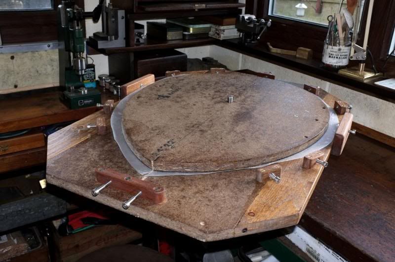
..Continuing on from last time then, All the parts of the frame former have been treated with waterproofer and here you see it all together for the first time.
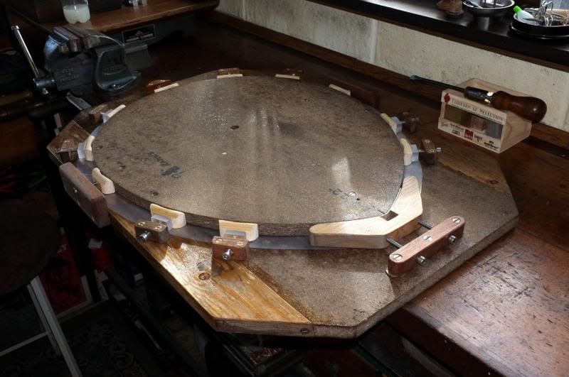
The actual shape former has been screwed down to the base and after taking some wise advice from other TFFers who have done this before, have interfaced some polythene sheeting between the two, to prevent glue sticking the net to the frame!
If the screws look a bit on the rough side, it's because they are all re-cycled ones removed from other things and cleaned up. In fact, all the materials used throughout this job are re-cycled products from scrapped items.
This is a better view of the former. I have to keep diving in-and out of the workshop to dodge the rain!!
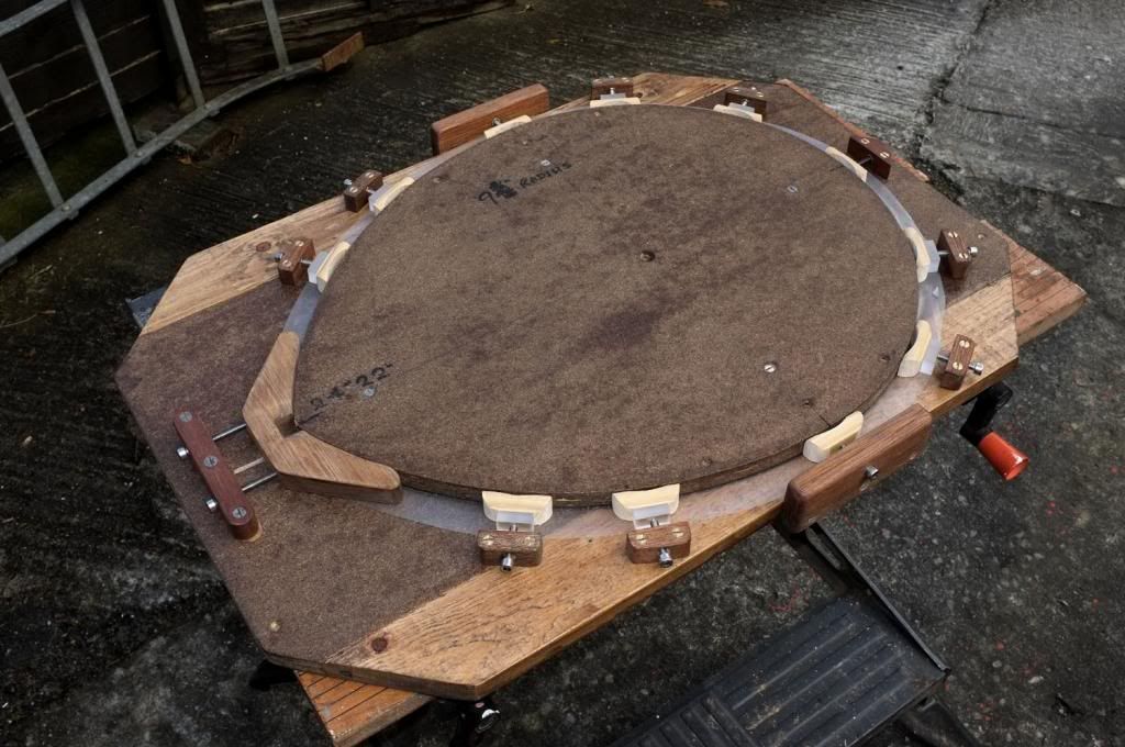
You will see that I have drilled a 12mm hole right through both former and base. After having a think about how to smoothly position the wood strips around the former whilst they are still hot, I thought that if a metal dowel were placed through the assembly and clamped in the vice, then instead of trying to manipulate the board and strips in a confined space, why not just rotate the board and feed the strips in to it?
The next project was to make a suitable steamer..
Initially, I was going to use my rod, bamboo strip dryer in a reverse capacity, i.e. to get wood wet instead of drying it out! After considering this again though, decided that it was never going to work successfully so have made a custom steamer for the job.
Have looked at all the ideas used by other net makers and instead of using a horizontal design, have decided to use the laws of physics in my favour and come up with this..!
Essentially, it is a vertical design, using the fact that hot air rises and water falls.
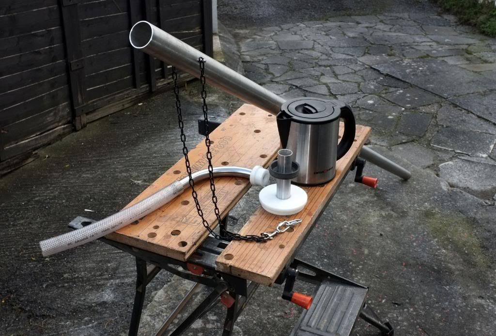
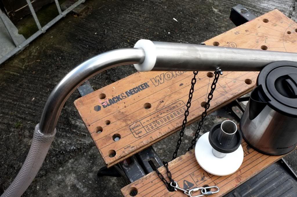
Firstly, I acquired an 8 feet length of 2" diameter, stainless steel tubing. This is the sort used for heating units and you can find lots of this sort of thing in scrap merchants yards, so no need to buy new. I made a restricting end fitting from a piece of 1" diameter stainless tube-which was already conveniently bent-and joined the two by turning up a piece of delrin. The fitting is only a sliding fit and not tight. Two small bolts were screwed into opposite sides of the main tube for attaching the chain.
This is for suspending the unit from a strong hook, screwed into the apex of the workshop roof (which is just high enough!) and accessed by step ladder. The vent tube on the end goes out through a top window to let out the steam to the outside world. The wood strips are simply threaded on to a piece of thin wire which is trapped accross the top of the tube and then suspended inside the big tube.
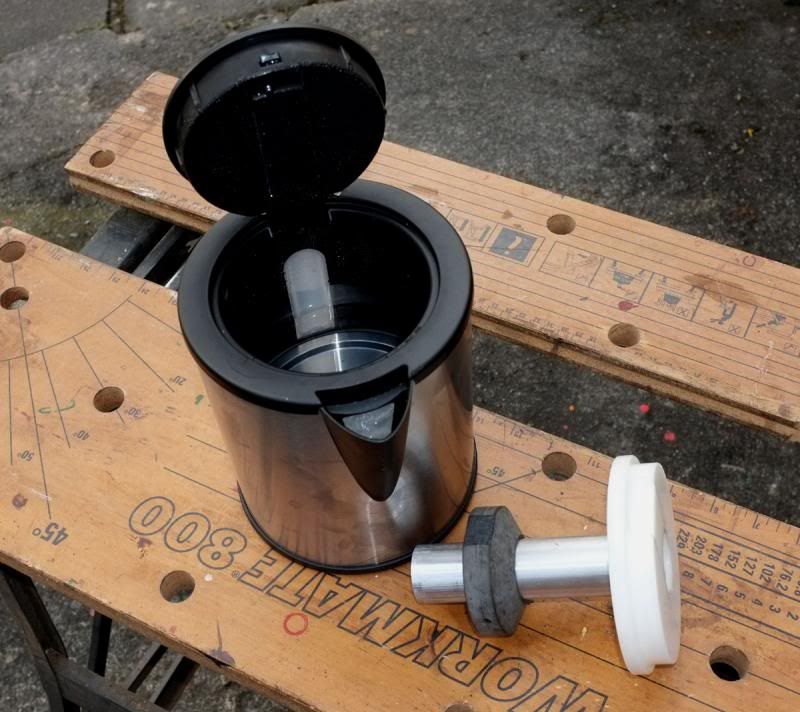
The steam source is very simple also. A low-power caravan kettle! This is only about 650 watts and delivers an ample amount of steam. I had to make a suitable adapter without ruining the kettle and made it as follows:-
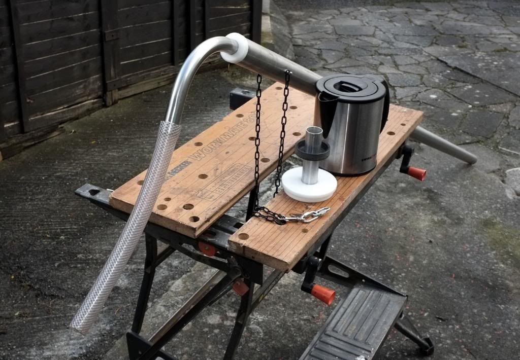
I firstly turned up a stepped diameter piece of delrin to fit the kettle, cutting away a relief for the hinge, and bored a hole in it big enough to accept a short length of aluminium tubing. On the side of the tubing I put some smaller holes and made a saucer-shaped piece from resin, which is a tight fit and pushed this on to just below the holes.
The reason for this is to trap and recycle the condensation from the tube. water drips (quite fast) from the tube, is caught by the saucer and then runs through the holes back in to the kettle..simples!
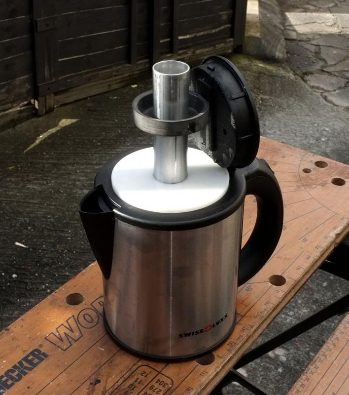
The WM+ Steamer Mark 1.
Well that's how it all goes together, now let's put it to the test..
I set up the steamer from the roof, positioned the outlet, filled the kettle and started up..
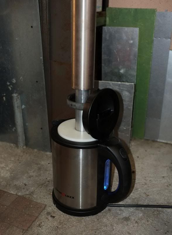
It needed a bit of careful height setting so that the tube from the kettle was only just inside the steamer tube. You can see it merrily boiling away on my workshop floor now and this low wattage kettle proved to be ideal! Steam was produced within a few minutes and at a good rate too. The main tube was untouchable without thick gloves within a few minutes and the condensation trap was working fine.
Initial tests showed that about 20 minutes steaming was the optimum time. The kettle capacity was easily enough for this and needed no further filling at all.
While this was happening, the former was prepared by putting the dowel in the vice and removing all the clamp blocks in readiness..
Right then, this is it....
The kettle was switched off and removed, the steamer taken down (with gloves!) and the wood strips removed.
These were then fed around the former..
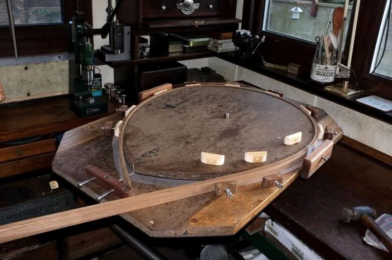
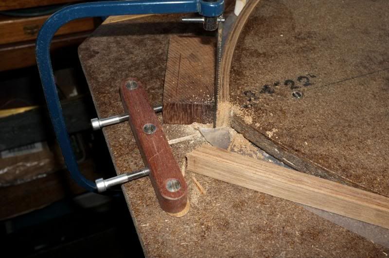
..the clamps loosely fitted and the excess wood ends roughly trimmed with a little saw, passing through a slot in the board.
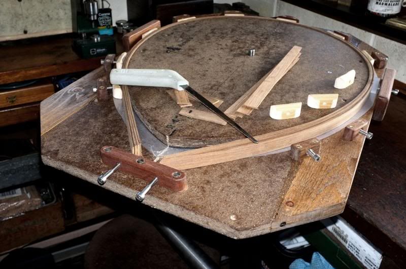
Panic over, the next thing was to trim up the ends a bit better with a fretsaw, so that the clamps could be correctly set, although this is not the finished size. Further trimming will be necessary after the strips have been glued together and this has been allowed for.
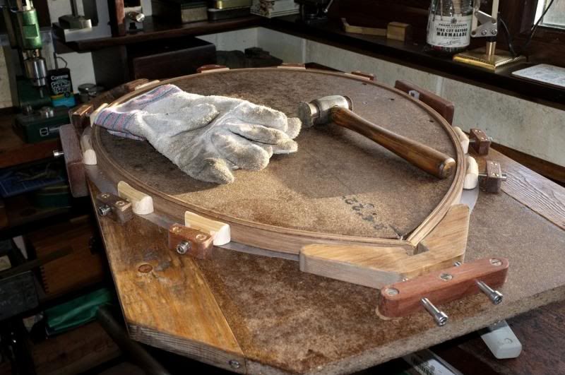
Now the end clamp is finally tensioned up to set the strips in the right shape..
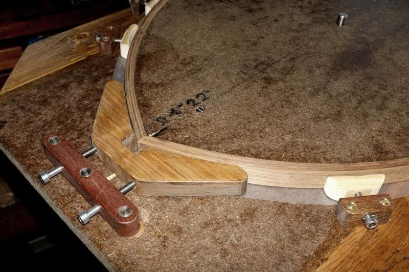
All in all, it all went very smoothly without panic and I am going to leave this clamped up for at least two weeks to thoroughly dry out. After that, the strips will be glued together and left to dry before planing down and finishing.
In retrospect, a few minutes longer in the steamer wouldn't have gone amiss but I think that this will be alright now.
In case you are wondering, the modified delrin lid on the kettle, plus the open top, prevented it from switch tripping out after boiling, but I stress that it was not left unattended and a constant check kept on the water level through the sight glass on the side (in blue).
The next job will be to make the brass yoke, or at least, get a bit further with it. I have now soldered the two 'arms' together-but that's for next time..
Regards from wm+
..Continuing on from last time then, All the parts of the frame former have been treated with waterproofer and here you see it all together for the first time.
The actual shape former has been screwed down to the base and after taking some wise advice from other TFFers who have done this before, have interfaced some polythene sheeting between the two, to prevent glue sticking the net to the frame!
If the screws look a bit on the rough side, it's because they are all re-cycled ones removed from other things and cleaned up. In fact, all the materials used throughout this job are re-cycled products from scrapped items.
This is a better view of the former. I have to keep diving in-and out of the workshop to dodge the rain!!
You will see that I have drilled a 12mm hole right through both former and base. After having a think about how to smoothly position the wood strips around the former whilst they are still hot, I thought that if a metal dowel were placed through the assembly and clamped in the vice, then instead of trying to manipulate the board and strips in a confined space, why not just rotate the board and feed the strips in to it?
The next project was to make a suitable steamer..
Initially, I was going to use my rod, bamboo strip dryer in a reverse capacity, i.e. to get wood wet instead of drying it out! After considering this again though, decided that it was never going to work successfully so have made a custom steamer for the job.
Have looked at all the ideas used by other net makers and instead of using a horizontal design, have decided to use the laws of physics in my favour and come up with this..!
Essentially, it is a vertical design, using the fact that hot air rises and water falls.
Firstly, I acquired an 8 feet length of 2" diameter, stainless steel tubing. This is the sort used for heating units and you can find lots of this sort of thing in scrap merchants yards, so no need to buy new. I made a restricting end fitting from a piece of 1" diameter stainless tube-which was already conveniently bent-and joined the two by turning up a piece of delrin. The fitting is only a sliding fit and not tight. Two small bolts were screwed into opposite sides of the main tube for attaching the chain.
This is for suspending the unit from a strong hook, screwed into the apex of the workshop roof (which is just high enough!) and accessed by step ladder. The vent tube on the end goes out through a top window to let out the steam to the outside world. The wood strips are simply threaded on to a piece of thin wire which is trapped accross the top of the tube and then suspended inside the big tube.
The steam source is very simple also. A low-power caravan kettle! This is only about 650 watts and delivers an ample amount of steam. I had to make a suitable adapter without ruining the kettle and made it as follows:-
I firstly turned up a stepped diameter piece of delrin to fit the kettle, cutting away a relief for the hinge, and bored a hole in it big enough to accept a short length of aluminium tubing. On the side of the tubing I put some smaller holes and made a saucer-shaped piece from resin, which is a tight fit and pushed this on to just below the holes.
The reason for this is to trap and recycle the condensation from the tube. water drips (quite fast) from the tube, is caught by the saucer and then runs through the holes back in to the kettle..simples!
The WM+ Steamer Mark 1.
Well that's how it all goes together, now let's put it to the test..
I set up the steamer from the roof, positioned the outlet, filled the kettle and started up..
It needed a bit of careful height setting so that the tube from the kettle was only just inside the steamer tube. You can see it merrily boiling away on my workshop floor now and this low wattage kettle proved to be ideal! Steam was produced within a few minutes and at a good rate too. The main tube was untouchable without thick gloves within a few minutes and the condensation trap was working fine.
Initial tests showed that about 20 minutes steaming was the optimum time. The kettle capacity was easily enough for this and needed no further filling at all.
While this was happening, the former was prepared by putting the dowel in the vice and removing all the clamp blocks in readiness..
Right then, this is it....
The kettle was switched off and removed, the steamer taken down (with gloves!) and the wood strips removed.
These were then fed around the former..
..the clamps loosely fitted and the excess wood ends roughly trimmed with a little saw, passing through a slot in the board.
Panic over, the next thing was to trim up the ends a bit better with a fretsaw, so that the clamps could be correctly set, although this is not the finished size. Further trimming will be necessary after the strips have been glued together and this has been allowed for.
Now the end clamp is finally tensioned up to set the strips in the right shape..
All in all, it all went very smoothly without panic and I am going to leave this clamped up for at least two weeks to thoroughly dry out. After that, the strips will be glued together and left to dry before planing down and finishing.
In retrospect, a few minutes longer in the steamer wouldn't have gone amiss but I think that this will be alright now.
In case you are wondering, the modified delrin lid on the kettle, plus the open top, prevented it from switch tripping out after boiling, but I stress that it was not left unattended and a constant check kept on the water level through the sight glass on the side (in blue).
The next job will be to make the brass yoke, or at least, get a bit further with it. I have now soldered the two 'arms' together-but that's for next time..
Regards from wm+
"Are not two sparrows sold for a farthing? Yet one of them shall not fall without your Father knoweth" ..Jesus of Nazareth, King James AV
-
MaggotDrowner

- Sea Trout
- Posts: 4032
- Joined: Sun Dec 16, 2012 11:32 pm
- 11
- Location: Nottinghamshire
Re: Making a Traditional Net..of sorts.
Looks great already! I love watching a talented craftsman at work.
"I'd rather be fishing!"
MD
MD
-
MGs

- Pike
- Posts: 6430
- Joined: Wed Nov 02, 2011 2:24 pm
- 12
- Location: Cornwall
Re: Making a Traditional Net..of sorts.
Fantastic as usual.
Old car owners never die....they just rust away
-
Paul F

- Sea Trout
- Posts: 4241
- Joined: Sat Jul 20, 2013 11:12 pm
- 10
- Location: The West Country
Re: Making a Traditional Net..of sorts.
I love watching this, it is beyond all my own capabilities, such skill shown 
-
AshbyCut

- Honorary President
- Posts: 10149
- Joined: Sun May 06, 2012 1:27 am
- 12
- Location: North Warwickshire
Re: Making a Traditional Net..of sorts.
It's a joy to watch this coming together. 
"Beside the water I discovered (or maybe rediscovered) the quiet. The sort of quiet that allows one to be woven into the tapestry of nature instead of merely standing next to it." Estaban.
-
Mark

- Head Bailiff
- Posts: 21238
- Joined: Mon Aug 22, 2011 4:55 pm
- 12
- Location: Leicestershire
- Contact:
Re: Making a Traditional Net..of sorts.
Very nice wm+, I can't wait for the next instalment.
Mark (Administrator)
The most precious places in the English landscape are those secretive corners,
where you find only elder trees, nettles and dreams. (BB - Denys Watkins-Pitchford).
The most precious places in the English landscape are those secretive corners,
where you find only elder trees, nettles and dreams. (BB - Denys Watkins-Pitchford).
-
GarryProcter

- Arctic Char
- Posts: 1898
- Joined: Sun Apr 29, 2012 12:48 pm
- 12
- Location: Wilt Shire
Re: Making a Traditional Net..of sorts.
As ever wm+, a delight to behold!
-
Northern_Nomad

- Arctic Char
- Posts: 1674
- Joined: Wed Nov 27, 2013 8:10 pm
- 10
- Location: Wales
Re: Making a Traditional Net..of sorts.
I have always had admiration for anyone who can make something of use or beauty.
The professional who brings years of training, knowledge and an intricate understanding of modern tools and machines to his craft and produces something which is perfect. But it his proffession and it is therefore somewhat expected. I suspect that everyone on here is very good at their chosen career and that is what is expected of us.
Next the artisan, who has the years of training but eschews the modern tools in favour of a bygone skill, more dependent on a "feel" or "eye" for things, who uses time and patience coupled with skill instead of modern computerised or overtly mechanical time saving aids. He also produces perfect products, sometimes with quirks that go with ancient arts. His skills are sometimes more pleasing.
And the amateur, the enthusiast, the hobbyist. Not doing his daytime job, but something he has a passion for and possibly limited time, no formal training, not always the correct or best tools and most of all has to overcome problems by ingenuity and lateral thinking. This is the true marvel.
WM Sir,
That will indeed be a wonderful net when finished. It will be a joy for you to use and cherish, plus will last you a lifetime and gain admirers. What they won't see however is the problem solving behind its building, no inclination of the application of one of the most powerful but understated fundamentals of homo sapiens; "neccessity is the mother of invention".
Really excellent stuff.
"We knelt side by side looking at it. I knew it was big, and suddenly it dawned on me it was more than that. It was tremendous!" - Richard Walker
-
Loop Erimder
- Wild Carp
- Posts: 9984
- Joined: Wed Apr 04, 2012 11:33 pm
- 12
- Location: Leicestershire
Re: Making a Traditional Net..of sorts.
Splendid in every way
Chance is always powerful. Let your hook be always cast; in the pool where you least expect it, there will be a fish