Making a float-making lathe.
-
MGs

- Pike
- Posts: 6417
- Joined: Wed Nov 02, 2011 2:24 pm
- 12
- Location: Cornwall
Re: Making a lathe..for making floats!
Totally astonishing
Old car owners never die....they just rust away
-
TemeLAD

- Crucian Carp
- Posts: 970
- Joined: Thu Jun 07, 2012 8:16 pm
- 11
Re: Making a lathe..for making floats!
Simply in awe! 
"I can't wait to buy a bamboo pole and a filament of line and a tube of breadcrumbs. I want to participate in this practice which allows a man to be alone with himself in dignity and peace. It seems a very precious thing to me".
John Steinbeck
John Steinbeck
-
DaveM

- Rudd
- Posts: 340
- Joined: Thu Oct 11, 2012 8:48 pm
- 11
- Location: London
Re: Making a lathe..for making floats!
As always..... very impressive work wm+
-
Estaban
Re: Making a lathe..for making floats!
Excellent work WM+, always learn something new when reading your updates, Well Done
Checked my Dremel.....Hencho en Mexico
Checked my Dremel.....Hencho en Mexico
-
Watermole+

- Chub
- Posts: 1050
- Joined: Thu Mar 15, 2012 11:07 pm
- 12
- Location: Devon & Cornwall border
Re: Making a lathe..for making floats!
Part 8. The 'Z' axis Adjuster (1)
...Once again, apologies for such a long delay between posts-Will try to narrow the gap from now on..
Firstly, a few words of explanation. On any kind of lathe, or similar machine, the left-and right axis, or movement of travel toward-or away from the motor, is known as the 'Z' axis.
The movement of travel across, away from-or back toward you in the same plane is known as the 'X' axis.
If it were to be possible to have vertical movement, this would be the 'Y' axis.
These axes of movement are accepted as the same universally.
In our case, the first thing to make is the means by which the cutting tool may be moved-positioned along the bed. This will be very basic; nothing like as sophisticated as a normal lathe, but will nevertheless have manual movement over about 5" and accurate to within 0.1mm (about 0.004"). This way, we should be able to maintain good repeatability.
After trying out several different ideas with wooden mock-ups, I eventually came back to the original drawing and have settled for that; a block holding the tool which is moved up-and down by means of a thumbwheel operated screw and guided along the centre rail, or bedway, the chosen position being fixed by a lock screw. It sounds complicated but you will see how it all unfolds and goes together in the next couple of chapters..
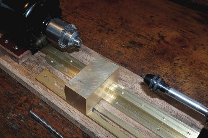
The first step was to start making the block which will eventually hold the cutting-or 'forming' tool. I would have liked to have used fine grain, cast-iron, but it was too expensive to buy a small piece. Believe it or not, I was given the scrap ends of a brass bar, which had been dumped in a skip; these may have had no use in industry, but they were good enough for this job. It's amazing what you can get, just by asking politely!
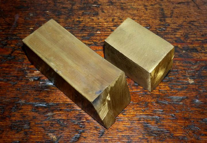
..and No, your eyes do not deceive you, the nearest one really is that bent!
I haven't taken pictures of every little stage, but the next thing was to put these blocks up in the 4-jaw chuck in the lathe and 'block them up' so all are true. The sizes do not matter at this stage. The bigger block was then marked out and clamped to the lathe cross slide in order that a slot could be cut to fit the centre rail of the lathe bed..
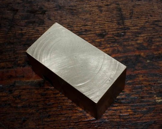
I'm not bothered about the circular 'turning marks' as the block must now be 'lapped in' flat, but using a sheet of 1200 grit on the surface plate.
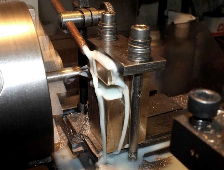
Now we try the block for fit on the rail. I have put a piece of flat steel of the right thickness underneath the brass block for temporary support.
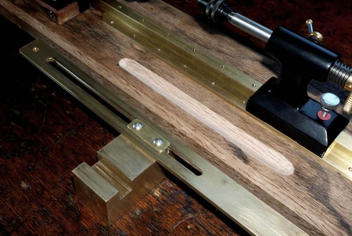
The next step is to make a means of moving it.
I started by 'milling' (using the lathe) a 3/16" wide slot in a piece of 1/8" thick, flat brass strip.
This will locate and travel within the slot by means of a Key set into the block. The key was made from 3/16" x 3/8" gauge-plate steel screwed into the block and held captive by a small brass plate on the outside (bear with me..).
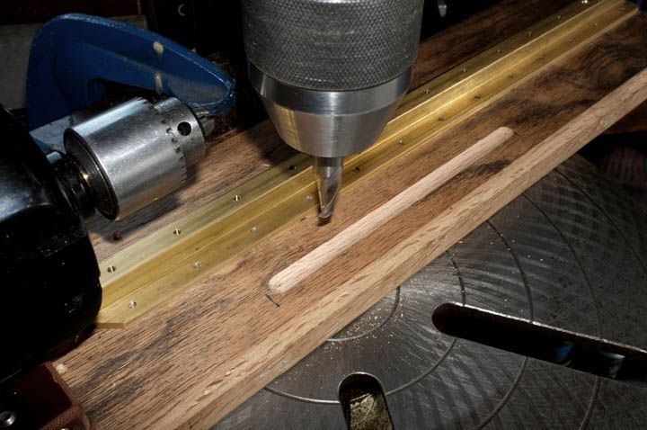
Next, it was necessary to cut a relief groove in the wood baseplate to prevent the little securing screws underneath from fouling. I did this by clamping a piece of wood as a guide rail to the drill table and then simply pushing the lathe bed along whilst the cutter did it's work!
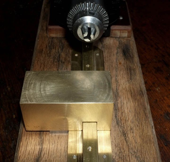
Now you see the result-and the slide piece temporarily assembled. Please note that it is in fact, upside down here!
Next, I made the adjuster screw from a piece of M6 x 1, stainless studding (bought from a model shop), determined the hole position in the brass block, then drilled & tapped an M6 thread right through it.
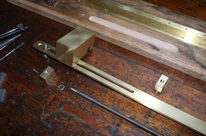
The adjuster screw is positioned and held captive at the motor end by a small brass block attached to the strip. This has been drilled through and the M6 studding has been turned to a good fit and then that itself drilled & tapped M3 to accept a button screw, as you see here..
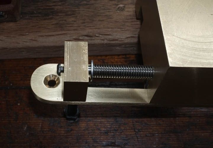
I have left the screw undone for clarity. The shocking finish to the countersunk hole WILL be put right soon!! I was trying to get something done for today and the drill was going a bit too fast, hence the 'chatter' of the countersink..
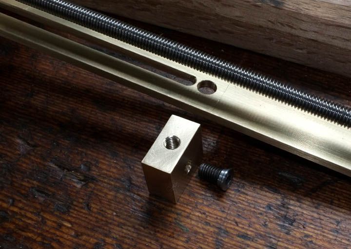
This is the detail of the other end. As you see, a similar support block arrangement which is fixed to the strip by a custom made, shoulder screw. The next step will be to cut the M6 studding to the right length, then turn it so that it goes through the support block and then make a thumbwheel to give you the means to turn the screw, thus moving the block as required.
Please note that none of these brass parts are completely finished yet. There is an awful lot still to do on this before we start on the actual tool holder, which must also have a means of travel along the 'X' axis, but that's for next time..
wm+
...Once again, apologies for such a long delay between posts-Will try to narrow the gap from now on..
Firstly, a few words of explanation. On any kind of lathe, or similar machine, the left-and right axis, or movement of travel toward-or away from the motor, is known as the 'Z' axis.
The movement of travel across, away from-or back toward you in the same plane is known as the 'X' axis.
If it were to be possible to have vertical movement, this would be the 'Y' axis.
These axes of movement are accepted as the same universally.
In our case, the first thing to make is the means by which the cutting tool may be moved-positioned along the bed. This will be very basic; nothing like as sophisticated as a normal lathe, but will nevertheless have manual movement over about 5" and accurate to within 0.1mm (about 0.004"). This way, we should be able to maintain good repeatability.
After trying out several different ideas with wooden mock-ups, I eventually came back to the original drawing and have settled for that; a block holding the tool which is moved up-and down by means of a thumbwheel operated screw and guided along the centre rail, or bedway, the chosen position being fixed by a lock screw. It sounds complicated but you will see how it all unfolds and goes together in the next couple of chapters..
The first step was to start making the block which will eventually hold the cutting-or 'forming' tool. I would have liked to have used fine grain, cast-iron, but it was too expensive to buy a small piece. Believe it or not, I was given the scrap ends of a brass bar, which had been dumped in a skip; these may have had no use in industry, but they were good enough for this job. It's amazing what you can get, just by asking politely!
..and No, your eyes do not deceive you, the nearest one really is that bent!
I haven't taken pictures of every little stage, but the next thing was to put these blocks up in the 4-jaw chuck in the lathe and 'block them up' so all are true. The sizes do not matter at this stage. The bigger block was then marked out and clamped to the lathe cross slide in order that a slot could be cut to fit the centre rail of the lathe bed..
I'm not bothered about the circular 'turning marks' as the block must now be 'lapped in' flat, but using a sheet of 1200 grit on the surface plate.
Now we try the block for fit on the rail. I have put a piece of flat steel of the right thickness underneath the brass block for temporary support.
The next step is to make a means of moving it.
I started by 'milling' (using the lathe) a 3/16" wide slot in a piece of 1/8" thick, flat brass strip.
This will locate and travel within the slot by means of a Key set into the block. The key was made from 3/16" x 3/8" gauge-plate steel screwed into the block and held captive by a small brass plate on the outside (bear with me..).
Next, it was necessary to cut a relief groove in the wood baseplate to prevent the little securing screws underneath from fouling. I did this by clamping a piece of wood as a guide rail to the drill table and then simply pushing the lathe bed along whilst the cutter did it's work!
Now you see the result-and the slide piece temporarily assembled. Please note that it is in fact, upside down here!
Next, I made the adjuster screw from a piece of M6 x 1, stainless studding (bought from a model shop), determined the hole position in the brass block, then drilled & tapped an M6 thread right through it.
The adjuster screw is positioned and held captive at the motor end by a small brass block attached to the strip. This has been drilled through and the M6 studding has been turned to a good fit and then that itself drilled & tapped M3 to accept a button screw, as you see here..
I have left the screw undone for clarity. The shocking finish to the countersunk hole WILL be put right soon!! I was trying to get something done for today and the drill was going a bit too fast, hence the 'chatter' of the countersink..
This is the detail of the other end. As you see, a similar support block arrangement which is fixed to the strip by a custom made, shoulder screw. The next step will be to cut the M6 studding to the right length, then turn it so that it goes through the support block and then make a thumbwheel to give you the means to turn the screw, thus moving the block as required.
Please note that none of these brass parts are completely finished yet. There is an awful lot still to do on this before we start on the actual tool holder, which must also have a means of travel along the 'X' axis, but that's for next time..
wm+
Last edited by Watermole+ on Sun Jun 16, 2013 10:06 pm, edited 1 time in total.
"Are not two sparrows sold for a farthing? Yet one of them shall not fall without your Father knoweth" ..Jesus of Nazareth, King James AV
-
Barney

- Grayling
- Posts: 733
- Joined: Thu Mar 28, 2013 12:09 pm
- 11
- Location: Woolwich, S/E London
Re: Making a lathe..for making floats!
Watermole,
you truly are a craftsman to be held in awe,thank you for sharing this with us,
Barney
you truly are a craftsman to be held in awe,thank you for sharing this with us,
Barney
-
Barney
- Grayling
- Posts: 733
- Joined: Thu Mar 28, 2013 12:09 pm
- 11
- Location: Woolwich, S/E London
Re: Making a lathe..for making floats!
i can't believe that the forum members have missed this episode of making this lathe,come on you lot before Watermole gives up on it,can't wait to see the next instalment.
-
Kingfisher

- Catfish
- Posts: 5772
- Joined: Sat Apr 07, 2012 4:14 am
- 12
- Location: Llandrindod Wells (Mid Wales)
Re: Making a lathe..for making floats!
I know, it looks shop bought.
WM you are a talented man.
WM you are a talented man.
God never did make a more calm, quiet, innocent recreation than angling.
Izaak Walton
-
Kevanf1

- Arctic Char
- Posts: 1563
- Joined: Sat Oct 06, 2012 2:22 pm
- 11
- Location: Cheslyn Hay, Staffordshire
Re: Making a lathe..for making floats!
Actually, I doubt you could buy anything with this good a finish in today's world. It would probably come from China, have far greater tolerances (as in much looser everywhere) and have rough bits everywhere one lookedKingfisher wrote:I know, it looks shop bought.
WM you are a talented man.
Currently reading......Go Fishing For Bass and Go Fishing For Skate and Rays both by Graeme Pullen, The Kill Switch by James Rollins, Raspberry Pi Manual - Haynes, 'Make: Electronics by Charles Platt' & the 'Myford series 7 manual by Ian Bradley'